VRscans | VRayScannedMtl
This page provides information on VRscans.
Page Contents
Overview
The VRayScannedMtl material applies material information gathered by the Chaos Group VRscans system to an object. The VRscans system captures the appearance of an actual physical material sample, going beyond single-point BRDF capture to faithfully represent the textured appearance of a real-world surface using bidirectional texture function (BTF) approximation. The information is saved in a .vrscan file, which the VRayScannedMtl material then reads to reproduce the material in the rendering.
The VRscans system and VRayScannedMtl material are intended as a solution for users who need to exactly match a given real-world sample.
The VRayScannedMtl material is designed to be used with a licensed version of the VRscans software. The material will still render without a license, but the material's UI will not display and any renderings will include a watermark.
The scanned material simply stores information about the way a physical material responds to light at individual points on the surface; it has no notion of components that extend across the surface such as diffuse or reflection qualities, or normal or bump maps. The scanned material is simply a faithful representation of how each point on the object responds to light. The .vrscan files tend to be quite large.
Currently, the material can render opaque and transparent surfaces. Also, aside from some general tint control, the material is unmodifiable; you can't change glossiness, increase reflectivity etc. You can only change the overall tint of the material.
For more details on VRscans, please see the VRscans documentation for information on downloadable sample scenes and Frequently Asked Questions, or visit the VRscans.com website.
UI Path: ||Material Editor window|| > Material/Map Browser > Materials > V-Ray > VRayScannedMtl
Parameters
General
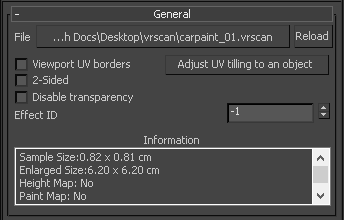
File – The file name with the data for the scanned material; usually has a .vrscan extension.
Reload – Refreshes the .vrscan file loaded in the material.
Viewport UV borders – Displays the borders of the material tile in the viewport on the objects that have the material applied. This only works with the DirectX viewports.
Adjust UV tiling to an object – The .vrscan file stores information about the physical size of the scanned sample. By clicking on a point over a given object, the texture tiling is modified so that the texture is the correct size for the clicked point.
2-Sided – Forces the back-facing polygons to be shaded in the same way as the front-facing ones. If this option is disabled, the back-facing polygons will appear black. This can be useful for objects like curtains. Note that this option is always considered enabled when rendering transparent materials.
Disable transparency – Disables transparency for materials that store such information. This can be useful for speeding up the rendering, especially when the transparency produces little or no effect.
Effect ID – Specifies the Effect ID number.
Information – Displays some useful information contained in the .vrscan file, such as the actual material sample size.
Appearance
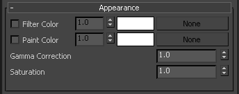
Filter Color – A color multiplier for the material sample and can be used to tint the material. (It will affect the color of the reflections as well. Acts as a post effect.)
Paint Color – Used to change the color of the material without losing the texture or changing the reflection color. For example, it can be used to changing the color of wood or leather without losing the material texture.
Gamma Correction – Adjusts the gamma of the material (including Filter Color and Paint Color if used) as a post effect.
Saturation – Controls the saturation of the material (including Filter Color and Paint Color if used) as a post effect.
Advanced
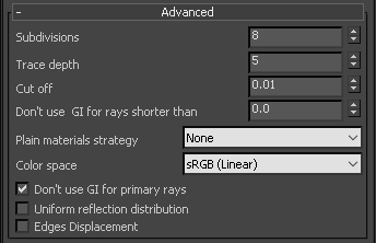
Subdivisions – Controls how many reflection rays will be traced for the material. Note that the material does not have a diffuse or reflection component and that everything is considered glossy reflection.
Trace depth – Controls the number of reflection bounces. A value of -1 means that the reflections bounces are controlled by the global V-Ray trace depth in the Global Switches rollout under the V-Ray tab in the Render Setup window.
Cut off – A threshold that is used to speed up reflections. If the contribution of reflections falls below this threshold, the reflections are not traced. This is similar to the Cutoff threshold of the VRayMtl material.
Don't use GI for rays shorter than – Defines the ray distance threshold below which GI caches will not be used to contribute for indirect illumination, but instead new secondary rays will be spawned. For example, if a ray hits any geometry that is too close to the ray's starting point, this will force the use of Brute Force GI for tracing additional secondary rays instead of using the GI cache.
Plain materials strategy – A strategy used for material display. It controls the visibility of textures (if present).
None – Used to view the material as it is with all the maps.
Average BRDF – Averages the BRDF and can be used to speed up the rendering for previews. Because texture details are removed, this also removes any tiling artifacts that might arise if the scanned sample does not tile very well. UV coordinates are still needed because most BRDFs are slightly anisotropic.
Average isotropic BRDF – Smooth representation of the material with no maps visible.
Scramble – Uses blocks from the photo samples in the material. Useful to reduce tiling artifacts for isotropic materials with small details like car paint with flakes.
Color space – Specifies between sRGB, Adobe RGB, and Pro Photo color space models.
Don't use GI for primary rays – GI caches will only contribute to indirect rays. By default, this option is enabled (i.e. GI is not used for primary rays) to ensure better realism of materials. It makes sense to disable this option when the scene lighting is relatively even from all directions, as it will speed up the rendering but will likely cause no loss of image quality.
Uniform reflection distribution – When enabled, the material reflections are computed by sampling the hemisphere uniformly. When disabled, importance sampling is used to put more rays in directions where the material contribution is larger. One option does not always perform better than the other; performance depends on the scene lighting and the particular material that is used.
Edges Displacement – Uses a special technique that makes the edges of the geometry appear slightly jagged inwards. This option is useful when rendering close-ups of materials with bumps. It is faster than actual displacement and helps to achieve better realism.
Clearcoat
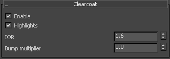
Enable – Enables the tracing of a clear coat layer for the material.
Highlights – Enables highlights from point light sources for the coat layer.
IOR – Determines the IOR of the coat layer, and from that controls the strength of the reflections. A value of 1.0 does not produce any reflections and disables the coat layer. Higher values produce stronger clear coat reflections. The .vrscan files typically contain the correct value for this parameter and it is set automatically when the file is loaded.
Bump multiplier – The coat layer has a built-in bump map stored in the material sample file. This allows you to control the strength of that bump.
Coordinates
This is a standard 3ds Max rollout used to control how the material is applied to objects.