Fire Rollout
This page provides information on the Fire Rollout for the Volumetric Options.
Page Contents
Overview
The Fire rollout controls the emissive color (fire) of the volumetric shader, and the light emitted by the VRayVolumeGrid. The color and intensity of the emission can be controlled and gradually transitioned between a physically correct appearance and an artistic appearance. Unlike the smoke color which needs an external light to become visible, fire will be visible immediately.
Unlike the smoke (Diffuse) color, which tells what fraction of the light is reflected by the volume and can't go above 1, the emissive color is an absolute value which can have values larger than 1. There are two parts to it - the color itself and its brightness (luminance). The final color is obtained by multiplying the two. Unlike the smoke color which needs an external light to become visible, fire will be visible immediately if you have set the color.
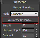
UI Path: ||Select V-Ray Volume Grid|| > Modify panel > Rendering rollout > Volumetric Options... button > Volumetric Render Settings window
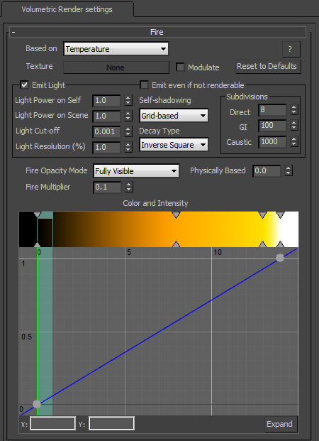
Fire
Based on – The source channel that will be rendered as fire. By default the Temperature option is used.
Disabled – Disables the emissive color.
Temperature – Uses the temperature channel.
Smoke – Uses the smoke channel.
Speed – Uses the magnitude of the velocity channel.
Texture – Uses an external texture map.
RGB – Uses a plain color.
Fuel – Uses the fuel channel.
Texture – If Based on is set to Texture, this slot specifies which texture to use.
Modulate – When the fire is not based on Texture and this option is enabled, the selected channel is multiplied by the map in the Texture slot.
Reset to Defaults – Resets the Fire settings to their default values.
Emit Light
The Emit Light section controls how the fire casts light on other objects in the scene as well as on the VRayVolumeGrid's smoke. If rendering using Global Illumination (GI), the fire will illuminate everything automatically, but the rendering will take quite long. Enabling Emit Light simulates GI by placing light sources in the bright parts of the fire, which gives similar results and renders much faster. The color and power of these lights are adjusted automatically but can be overridden. Illumination of the smoke can be controlled by the VRayVoumeGrid's fire with the Self-shadowing option. If it is enabled, the smoke will obstruct the path of light from the fire, creating a much more realistic look, but decreasing rendering performance. Approximating grid-based self-shadowing can be used to gain back rendering speed.
Emit Light – Enables all the light-emitting options and enables the fire to shine on the smoke and on surrounding objects in the scene.
Emit even if not renderable – When enabled, the VRayVolumeGrid will be forced to emit light even if the rendering is disabled. This can be used for compositing when the fire is rendered in a separate pass.
Light Power on Self – Controls the power of the light on the VRayVolumeGrid's smoke. This value does not change the strength of the fire, only the illumination it produces on the smoke.
Light Power on Scene – Controls the power of the light on all scene objects except the VRayVolumeGrid itself.
Light Cut-off – Same as the Cutoff parameter for a VRayLight. This parameter specifies a threshold for the light intensity, below which the light will not be computed. This value can be useful for limiting the effect of the fire to some distance around the VRayVolumeGrid. Larger values cut away more light; lower values make the light range larger. If 0.0 is specified, the light will be calculated for all surfaces, but the rendering will slow down.
Light Resolution (%) – Specifies the resolution of the light grid as a percentage of the fire grid. Perfect illumination from fire could be achieved by placing an Omni light in each fire cell, but this could take a tremendous amount of time to render and is usually not necessary to approximate the fire's illumination convincingly. For this reason, a separate light grid is created internally which can have a lower resolution than the fire grid, and this light grid is populated with an Omni light in each cell. The lower resolution (and thus fewer Omni lights) speeds up rendering at the expense of some illumination detail, which might not always be visible anyway. At a value of 100, the light grid has the same resolution as the fire grid. The more this value is decreased, the smoother the illumination will become and the faster the rendering will be, but at very low values the fire might not blend well with the light it casts on the smoke. See the Grid-based Self-shadowing with Light Resolution (%) example below.
Self-shadowing – Enables self-shadowing of the smoke from the light of the fire. If this option is enabled, enabling the Scattering option in the Smoke color rollout will generally help the light to illuminate a larger portion of the smoke, creating a more realistic self-illumination effect.
None – Smoke will not obstruct the light propagation and will be brightly lit.
Ray-traced – The same mechanism that illuminates the scene geometry will be used on the smoke as well. This mode is physically correct and takes into account non–transparent obstacles inside the volume, but requires intense computation and might take considerable time to render.
Grid-based – The self-illumination of the smoke will be calculated separately from the light that the fire casts on the scene using an approximated fast formula. While the Ray-traced option might produce noise, this option has no such effect; the resulting illumination on the smoke is always smooth. However, any obstructing obstacles inside the volume are ignored by this mode. The Light Resolution (%) parameter can be used to lower the resolution of the light grid and further speed up the illumination process. Reducing the grid will generally make for smoother self-illumination.
For more information, see the Self-shadowing example below.
Decay type – Controls the way in which the VRayVolumeGrids emissive light fades as it moves away from the emitter:
None – The light does not fade at all, unless obstructed.
Inverse – The light intensity fades with the inverse of the distance. For example, at a distance of 5 units the intensity will be 1/5th of the intensity of the emitter.
Inverse square – The light fades with the inverse square of the traveled distance. For example, at a distance of 5 units the intensity will be 1/25th of the intensity of the emitter. This is physically correct light decay.
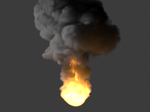
Example: Self-shadowing
Self-shadowing = None
(render time = 2 min)
Self-shadowing = Ray-traced
(render time = 17 min)
Self-shadowing = Grid-based, Light Resolution (%) = 10
(render time = 1 min)
Example: Grid-based Self-shadowing with Light Resolution (%)
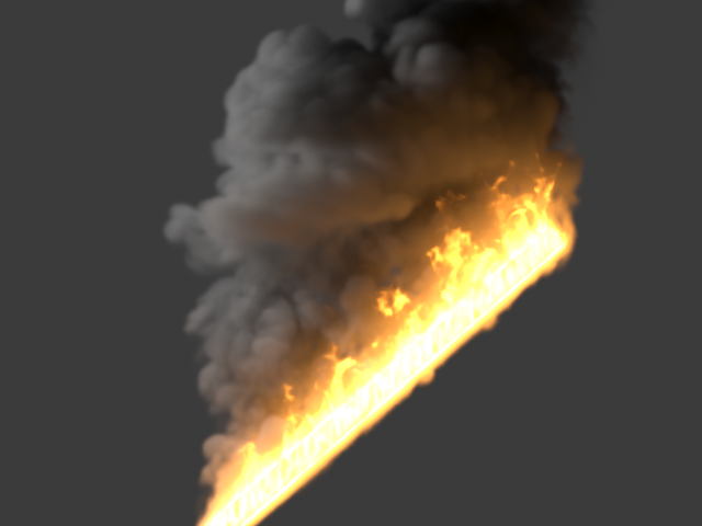 Self-shadowing = Grid-based, Light Resolution (%) = 1%
(render time = 40 secs)
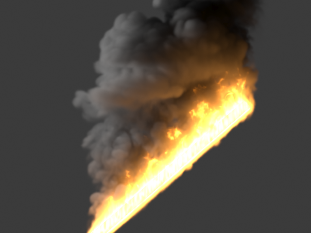
Self-shadowing = Grid-based, Light Resolution (%) = 10%
(render time = 58 secs)

Self-shadowing = Grid-based,
Light Resolution (%) = 100% (no reduction)
(render time = 6:39 mins)
Subdivisions
The parameters in the Subdivisions section control the number of rays to be traced in order to calculate the lighting. The bigger the number of the rays, the better the result. The rendering, however, will be slower. For a general explanation of how light sampling works, see the DMC Sampler page.
Direct – This parameter controls the number of rays traced when calculating soft shadows cast by the fire. Higher values increase shadow quality and also increase render times. Lower values speed up the rendering but produce more noise in soft shadows. If the value is set to 0 all emissive lights are sampled, which can make rendering quite slow for a large number of emissive lights.
GI – Indirect light sampling control. This parameter controls the number of rays traced from the fire to the scene when GI is calculated. For example, if a global photon map is being used, this value controls the photon count.
Caustic – Caustic sampling control. Similar to the GI parameter, but used to set caustics subdivisions when caustics are calculated.
Additional Parameters
Fire Opacity Mode – While smoke has its own opacity in the Smoke Opacity rollout, fire's opacity can be determined in either of three ways:
Use Smoke Opacity – Fire will use the same opacity that is set to the smoke in the Smoke Opacity rollout. This way the fire will not be visible in cells where there is no smoke.
Fully Visible – Fire will always use opacity of 1.0, regardless of the smoke's opacity.
Use Own Opacity – A varying opacity can be set for the fire using the Opacity diagram.
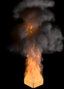
Physically Based – Transitions between artistic look of the fire (when set to 0) and realistic physically based Intensity (when set to 1). The realistic mode multiplies the fire intensity by the Black Body Radiation model, which gives strong brightness to the hot parts of the fire. The example below uses the settings from the miniature image on the right. For more information, see the Physically Based example below.
Fire Multiplier – General multiplier for the fire intensity.
Opacity Multiplier – General multiplier for the fire's opacity as set by the opacity function represented in the diagram. Available only when Fire Opacity Mode is set to Use Own Opacity.
Color and Intensity Diagram
At the bottom of the Fire rollout is a gradient for setting the color, and a diagram for setting either the intensity or opacity of the fire depending on the Fire Opacity Mode selection. The selected channel's data range is denoted by a blue-green line.
Color – The color gradient represents the color of the light as a function of the selected channel's value. The selected channel's data range is denoted by a blue-green line.
Intensity – The luminance of the emitted light is determined by the function represented in the diagram control below the color gradient when the Fire Opacity Mode is set to Use Smoke Opacity or Fully Visible. Along the X axis is the value of the selected source channel (Temperature, Fuel, etc.). Values are multiplied by the colors and by the Fire Multiplier value to achieve the real value that will be used. Values are also affected by the Physically Based value if other than 0.
Opacity – The opacity of the emitted light is determined by the function represented in the diagram control below the color gradient when the Fire Opacity Mode is set to Use Own Opacity. Along the X axis is the value of the selected source channel (Temperature, Fuel, etc.). Values are multiplied by the colors and by the Opacity Multiplier value to achieve the real value that will be used. Values are also affected by the Physically Based value if other than 0.
Expand – When a graph is displayed, click this button to open a resizeable pop-up window showing just the graph.
Diagram and Gradient controls
The following controls can be used in the color gradients and diagrams:
Double click – Creates a new point or changes an existing one.
Left button drag – Moves the selected point(s).
Left button drag over the left or bottom rulers (diagrams only) – Scale the diagram in the corresponding direction.
Middle button drag over the background – Drags the visible area. If the Ctrl key is pressed, the background can be dragged instead, thus transforming the diagram.
Mouse wheel – Zoom in/out. If the Ctrl key is pressed, the zoom will occur on the background instead, thus transform the diagram.
Right click – Brings out a drop-down menu where points can be added, edited, or deleted, fit the entire diagram or gradient into the view, clear the diagram, and load and save the diagram it to a file.
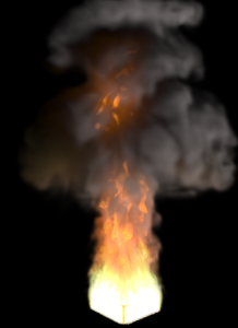
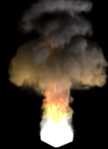
Example: Physically Based Lighting
Physically Based = 0
Physically Based = 0.1
Physically Based = 1